
Views: 0 Author: Site Editor Publish Time: 2026-10-13 Origin: Site


Designing folded metal components creates a fundamental tension for engineering teams. Over-specifying limits drives manufacturing costs up exponentially. Conversely, under-specifying them leads to frustrating assembly failures. Entire production batches might face costly rejection.
Many professionals forget sheet metal behaves differently than machined bar stock. Inherent variables dictate realistic manufacturing limits on the shop floor. Material grain direction shifts. Raw gauge thicknesses fluctuate. Metal springback forces constant machine adjustments. You cannot hold a folded flange to the exact same dimensional standard as a milled pocket.
This guide provides a proven framework for defining achievable dimension ranges. You will learn how to balance strict functional requirements against cost-effective fabrication methods. We will explore material behaviors, drawing best practices, and actionable strategies. Following these guidelines ensures seamless production and highly reliable part fitment.
Standardizing bend tolerances reduces lead times and prevents unnecessary premium charges from fabricators.
Material thickness, alloy type, and bend radius directly impact the achievable precision of any folded feature.
Specifying critical-to-function dimensions while relaxing non-critical areas is the most effective way to control production costs.
Clear, unambiguous custom sheet metal fabrication drawings minimize vendor RFQ friction and quality disputes.
Engineering teams frequently face a common business problem during the design release phase. They often leave default CAD title block numbers completely untouched. A standard ±0.005" linear callout inadvertently forces basic brackets into high-precision manufacturing tiers. This innocent oversight multiplies your unit price unnecessarily. It demands specialized tooling setups. Operators must perform slower press brake cycles to hit arbitrary targets. You end up paying aerospace prices for simple commercial brackets.
You must understand the physical reality of the modern press brake. Bending metal differs entirely from milling solid aluminum blocks. Standard sheet metal bending tolerances are inherently looser than CNC machining limits. We must account for material springback after the punch releases downward pressure. Punch and die wear happens naturally over long production runs. Furthermore, raw sheet gauge naturally varies directly from the steel mill. These physical factors make absolute perfection incredibly expensive and virtually impossible across large batches.
We need clear success criteria for any new product introduction. What does a successful specification actually look like? A successful specification achieves 100% assembly fitment on your final production line. Crucially, it hits this fitment metric at the lowest viable manufacturing cost tier. You must balance mechanical function against actual fabrication reality. Good design embraces the natural variations of folded metal.
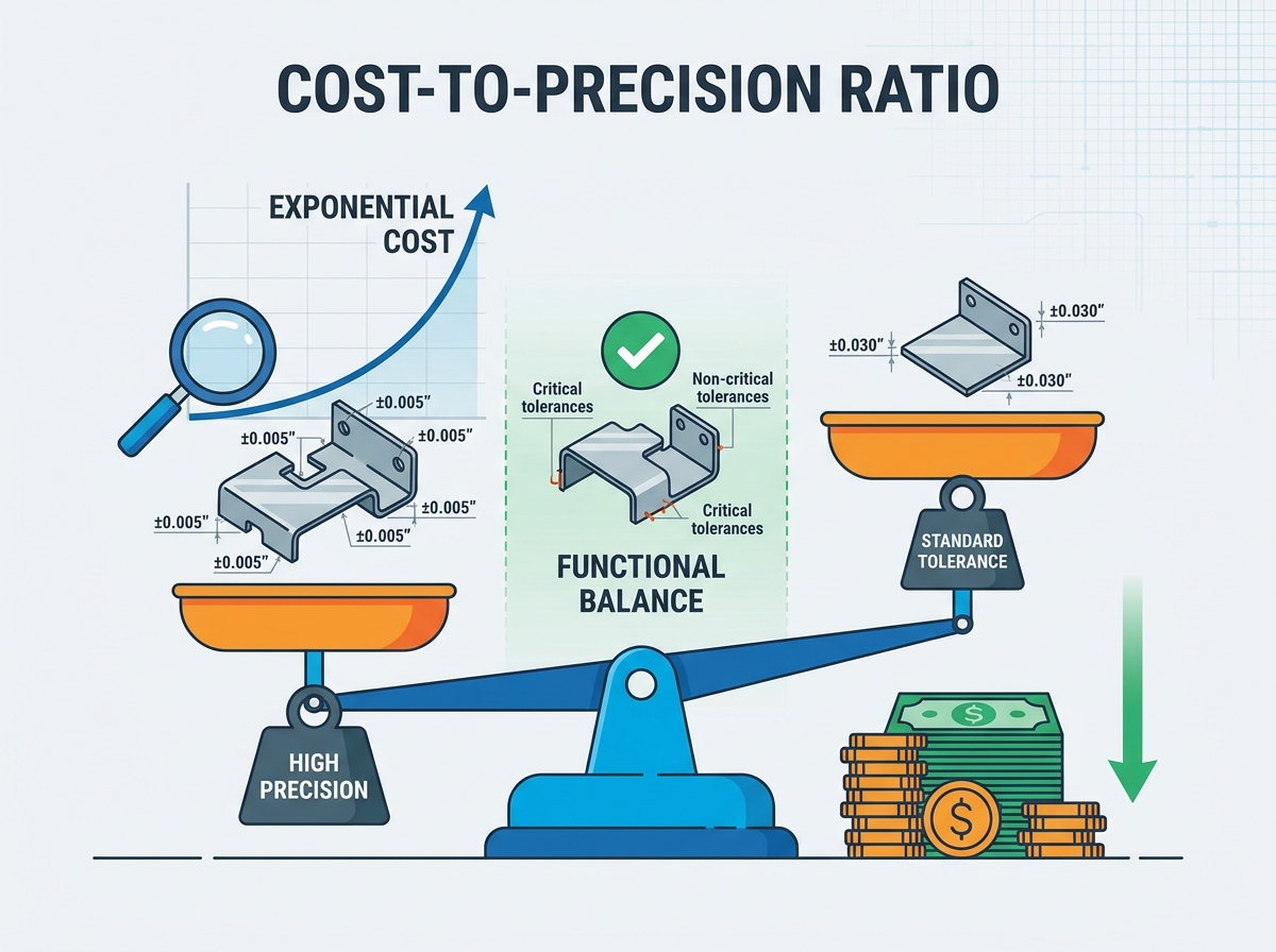
You must deliberately categorize your project needs before sending out requests for quotes. We break solutions down into standard commercial fabrication versus strict precision requirements. Each category serves vastly different functional applications. Choosing the wrong tier guarantees budget overruns or assembly floor headaches.
Standard commercial limits offer highly sensible ranges for most industrial applications. Angular variations typically hold around ±1.0°. Linear dimensions usually maintain ±0.015" to ±0.030" depending on overall part size. You should specify standard limits for basic enclosures. They work perfectly for internal mounting brackets. Non-mating structural components also benefit greatly from these cost-effective ranges. Fabricators achieve these numbers using standard air bending techniques. They use off-the-shelf tooling. Setup times remain extremely brief.
Sometimes your design demands much more. When you require true precision sheet metal parts, the acceptable limits tighten significantly. Angles reach an impressive ±0.5°. Linear dimensions shrink down to ±0.005" or ±0.010". These tight ranges suit complex aerospace components. They fit tight-tolerance electronic chassis perfectly. Automated assembly line mechanisms also require this strict control to prevent robot handling errors.
Engineers must heed a crucial risk warning here. Precision tiers demand expensive preparation. They often require custom ground tooling. Operators must perform multiple test bending runs. Fabricators must use advanced CNC press brakes. These machines feature active laser angle measurement systems. These extra quality assurance steps drive up unit economics rapidly. You pay a high premium for every incremental improvement in accuracy.
| Specification Category | Standard Fabrication | Precision Fabrication |
|---|---|---|
| Angular Tolerance | ±1.0° | ±0.5° |
| Linear Tolerance (Short lengths) | ±0.015" | ±0.005" |
| Linear Tolerance (Long lengths) | ±0.030" | ±0.010" |
| Ideal Application | Brackets, basic enclosures | Aerospace, electronic chassis |
| Tooling Requirement | Standard V-dies | Custom ground precision dies |
You must evaluate specific features carefully during the drafting phase. These dimensions link directly to your final assembly outcomes. Controlling them ensures your parts fit together perfectly on the shop floor.
Bend Angles: You specify angular variation based on material memory. Tighter inner radii increase mechanical stress. You must account for springback variations. Different alloy batches behave differently under the die. For example, 5052 aluminum springs back differently than 304 stainless steel. Operators compensate for this by slightly over-bending the material.
Flange Lengths (Edge-to-Bend): Always originate your dimensioning datum correctly. Pull dimensions from the inside or outside of the bend. Never use the bend centerline. Centerlines vanish in the physical world. Fabricators cannot accurately measure a physical part from an imaginary space in the air. Inspecting an inside edge provides a hard, reliable reference point.
Hole-to-Bend Distances: Placing a hole too close to a bend line risks severe distortion. The metal stretches forcefully during the forming process. A perfectly round hole easily becomes an unusable oval. Follow strict minimum setback rules for reliable results. Keep features safely away from the primary deformation zone.
Material Thickness Variation: Mill variations on raw gauge directly affect the final folded dimensions. Steel mills sell sheet metal within an acceptable thickness band. A 16-gauge sheet might measure 0.055" today and 0.063" tomorrow. This issue compounds rapidly on multiple overlapping bends. A simple U-bracket might grow much wider than expected. It happens naturally if the raw sheet runs on the thicker end of its commercial specification.
Implementation considerations dictate your overall manufacturing success. Proper documentation prevents vendor disputes. It accelerates production timelines significantly. Follow these established industry guidelines.
Avoid Stacked Tolerances: Chaining dimensions across multiple bends compounds your error margin. A ±0.010" limit on three consecutive bends becomes a ±0.030" total variance. Always advocate for baseline or datum dimensioning instead. Pull all critical measurements from a single established zero point.
Identify Datums Strategically: Choose datums based on actual mating conditions. Look at how the part sits in the final assembly. Pinpoint the primary mounting face. Use it as your foundational reference plane. This strategy aligns manufacturing priorities with functional realities.
Specify Only What Matters: Identify your "Critical to Quality" (CTQ) features. Highlight these specific areas clearly on your custom sheet metal fabrication drawings. Let all non-critical features default to standard commercial limits. This approach saves money immediately. It stops fabricators from wasting time inspecting irrelevant dimensions.
Address K-Factor and Bend Deduction: Designers often try to estimate K-factors in CAD software. However, your final drawing should only dimension the finished part. Leave the flat pattern calculations entirely to the fabricator. Their specific punch and die sets dictate the exact bend deduction. Forcing a flat pattern upon a manufacturer restricts their ability to hit your final 3D requirements.
You need to verify your manufacturing partner comprehensively. Can they actually hit your specified targets consistently? An impressive website does not guarantee precision capabilities. Ask specific technical questions.
Ask potential vendors about their specific press brake technology. Look for multi-axis CNC backgauges. Check if they utilize active laser angle correction during the bend cycle. Modern equipment compensates for springback in real time. Older mechanical brakes rely entirely on operator skill and guesswork. Advanced machinery reduces scrap rates dramatically.
Verify how they handle First Article Inspections (FAI). Do they rely solely on manual calipers and protractors? The best fabricators use automated optical comparators. They might use laser Coordinate Measuring Machines (CMMs) for complex geometries. Automated measuring removes human error from the inspection loop. It provides verifiable, digital proof of compliance.
Assess their nesting practices. Do they control grain direction across the sheet? Bending against the grain yields vastly different springback than bending parallel to it. It also affects material cracking risks on harder alloys. Consistent grain orientation directly impacts bend repeatability across a massive production run.
Advise your engineering team to request a Design for Manufacturability (DFM) review. Do this collaboratively with your shortlisted vendor before freezing the final revision. A quick thirty-minute conversation prevents incredibly expensive redesigns later. Let the fabricator suggest minor geometrical tweaks. These small changes often yield massive cost savings.
Perfect outcomes require a true collaborative effort. You must blend the design engineer's functional intent with the fabricator's physical tooling realities. Rigidly forcing unachievable limits creates friction and wastes capital.
We strongly encourage a complete mindset shift across your engineering department. Move away from "tightest possible" constraints. Embrace "functionally appropriate" specifications instead. This targeted approach saves valuable time. It slashes your unit costs without sacrificing final product quality.
Review your current component models today. Submit your 3D models and 2D layouts for a technical DFM review. Engage with a qualified manufacturing partner. Get an instant quote to see exactly how optimized specifications reduce your bottom line.
A: Baseline industry standards typically fall around ±0.015 inches for linear dimensions. Angular dimensions generally hold ±1.0 degree on standard gauge steel. These commercial limits provide a highly reliable balance. They ensure good fitment while maintaining affordable manufacturing costs for most general enclosure applications.
A: Thicker materials require wider bottom V-dies during the forming process. Furthermore, heavy-gauge sheet metal exhibits more pronounced thickness variations straight from the mill. These combined factors result in much wider tolerance bands. Tight precision becomes significantly harder to achieve on thick plates compared to thin-gauge materials.
A: We advise against dimensioning the flat pattern tightly on your final prints. Your fabricator needs flexibility. They must adjust flat layouts and bend deductions based on their specific press brake tooling. Focus your drawing entirely on the finished part dimensions to guarantee proper assembly fitment.
A: As a general rule of thumb, keep the edge of any hole at least 2.5 to 3 times the material thickness plus the bend radius away from the bend line. This vital setback prevents the hole from stretching, tearing, or distorting during the bending operation.


