
Views: 0 Author: Site Editor Publish Time: 2026-09-25 Origin: Site


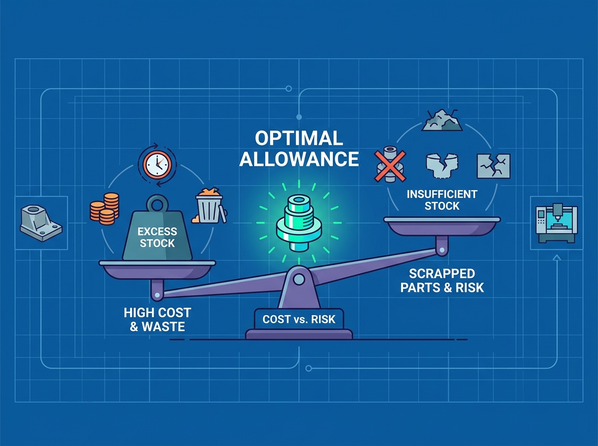
Manufacturing teams face a high-stakes balancing act when they transition raw parts to the machine shop floor. Leave too much material on your blanks, and you rapidly inflate manufacturing expenses. You waste valuable time cutting excess metal. Conversely, leave too little material, and you risk scrapping entire batches. These parts fail because they cannot clean up properly during final cuts.
We define casting machining allowance, or stock allowance, as the deliberate excess material designed into a raw blank. Manufacturers add this material to ensure they meet critical dimensions and surface finishes during secondary operations.
This guide serves as a definitive framework for engineers and procurement teams. You will learn how to calculate optimal stock limits and optimize your requests for quotation (RFQs). We aim to help you bridge the gap between foundry capabilities and CNC machine shop realities. By mastering these principles, you can secure reliable production runs and protect your bottom line.
Optimal casting machining allowance is not a static number; it depends on part size, casting method, material shrinkage, and required final tolerances (e.g., ISO 8062 standards).
Overestimating stock increases CNC cycle times and tool wear, severely impacting unit economics.
Underestimating stock fails to account for casting variations (shift, warp, or shrinkage), leading to unusable parts.
Integrating casting and machining under a single vendor minimizes datum alignment disputes and scrap liability.
Engineers often struggle to find the perfect middle ground when designing blanks. Every millimeter of extra metal carries a hidden price tag, yet every missing fraction of a millimeter carries extreme risk. Understanding this financial impact helps you make better engineering decisions.
Over-engineering your stock levels seems like a safe bet initially. However, excessive material creates a cascading effect of negative financial consequences on the shop floor.
Increased roughing passes: Machinists must program additional tool paths to remove the extra metal. This bloats your cycle times significantly.
Longer machine cycle times: Time is money in any machine shop. When a mill spends an extra five minutes roughing out unnecessary stock on every unit, you lose throughput.
Accelerated cutting tool wear: Carbide inserts degrade faster when they plow through heavy, unnecessary material. You will pay for more frequent tool changes.
Higher shipping weights: Extra metal adds up quickly across thousands of parts. You will pay more for freight and logistics.
Material waste: You pay the foundry for raw metal, only to pay the machine shop to turn it into chips.
Trying to save money by trimming the buffer too closely often backfires. Skimping on stock introduces severe quality control risks.
Black spots: These occur when unmachined raw surfaces remain on critical faces. The tool simply does not have enough material to cut into, leaving the rough exterior intact.
Setup failures: A tight buffer leaves no room for error. Machinists cannot compensate for core shift, mold mismatch, or thermal distortion during the initial setup.
Scrapped batches: A part missing just 0.1mm of material on a critical sealing face is completely useless. You lose the entire investment in that specific piece.
Professionals frequently confuse these two terms, but they serve entirely different purposes. Tolerance dictates the acceptable deviation of a finished dimension. For example, a bored hole might have a tolerance of ±0.05mm. Allowance, on the other hand, is the physical extra stock required on the raw blank to achieve that tolerance reliably. You add allowance to guarantee you can meet the tolerance.
You cannot use a universal rule of thumb for every project. Several core variables interact to determine exactly how much buffer you need. By analyzing these factors, you can design a more robust manufacturing plan.
The method you choose to create the raw blank heavily influences the required buffer. Different processes offer varying levels of inherent precision.
Standard Allowance by Process Type
| Process Type | Inherent Precision | Typical Stock Required |
|---|---|---|
| Investment Casting | High (Near-net shape) | 0.5mm – 1.5mm |
| Die Casting | High (Near-net shape) | 0.5mm – 1.5mm |
| Sand Casting | Low to Moderate | 2.0mm – 5.0mm+ |
Investment and die processes produce near-net shapes. They require minimal stock because they hold tight dimensions right out of the mold. Sand processes require larger buffers to account for mold shift, aggressive draft angles, and much rougher surface finishes.
Dimensional scale exponentially increases the required buffer. As parts get larger, they warp more during the cooling phase. A massive engine block experiences far more thermal distortion than a small pump housing. You must increase the buffer to account for this predictable warpage.
Furthermore, you must account for draft angles in your calculation. Draft is the taper applied to vertical walls so operators can remove the pattern from the mold. Surfaces furthest from the parting line become thicker. Therefore, these deep features inherently carry more stock. You must calculate your buffer starting from the thickest point of the drafted wall.
Subjective guessing leads to manufacturing disputes. Professionals rely on industry standards to establish objective baselines. ISO 8062 defines Required Machining Allowance (RMA) grades. These grades provide specific millimeter values based on the largest dimension of your part and the chosen alloy. Referencing these standard grades allows you to align expectations clearly with your manufacturing partners.
The alloy you pour dictates how the metal behaves during cooling and cutting. You must tailor your buffer strategy to the specific metallurgical properties of your material.
Steel presents unique challenges in the foundry. It features a notoriously high shrinkage rate during solidification. This severe shrinkage pulls critical features out of their intended locations. Consequently, determining the proper machining allowance for cast steel requires a conservative approach. You must leave a larger buffer to guarantee full clean-up after thermal distortion takes its toll.
Additionally, steel surfaces often develop tough oxide skins, hard spots, and minor sand inclusions. Machinists cannot take light, delicate cuts on this surface. A shallow cut causes the tool insert to rub against the abrasive outer layer, leading to rapid tool failure. You need enough buffer depth to allow the cutting tool to plunge beneath this abrasive skin on the very first pass. This aggressive first cut protects the tooling and stabilizes the process.
Iron behaves quite differently from steel. Gray and ductile irons offer relative stability and predictability during the cooling phase. They shrink less aggressively, which means they warp less. This stability allows you to tighten the stock buffer compared to steel alternatives.
When you focus on CNC machining cast iron parts, you benefit from the metal's internal structure. The graphite flakes embedded in cast iron act as a natural lubricant. Because iron cuts so smoothly, leaving slightly larger allowances proves less penalizing on your tool life. The inserts survive the extra passes. However, you must still optimize the buffer. Even though the tools survive, excessive roughing passes still consume valuable cycle time, which remains a critical commercial factor.
Even with perfect engineering, real-world blanks exhibit variation. Batch-to-batch inconsistencies are a fundamental reality of metalcasting. The success of your project depends on how the machine shop handles these natural variations.
A successful machining operation begins with intelligent datum targets. You must design proper datum points on the raw blank to ensure consistent fixturing. A datum target represents a specific, localized point where the fixture grips or rests against the raw metal. By defining exact points rather than broad surfaces, you guarantee the part aligns perfectly in the machine, regardless of minor surface irregularities. This strategy locks the part in the exact same orientation every time.
Modern machine shops employ advanced technology to fight variation. Using in-machine probing systems, such as Renishaw units, machinists can dynamically adjust to each unique blank. Before the first tool path begins, the spindle lowers a delicate probe to touch critical raw surfaces.
The software calculates the true center and orientation of that specific piece. If a core shifted slightly in the foundry, the probe detects it. The machine then shifts its entire coordinate system to match the reality of the physical part. This adaptive approach saves countless parts from the scrap bin.
The first production run always reveals hidden truths. You must establish iterative feedback loops between the machine shop and the foundry. When the initial CNC run exposes actual distortion patterns, the machinist must communicate these findings back to the foundry engineers.
Perhaps a flange warps predictably in one direction. Instead of scrapping parts, the foundry can adjust the tooling or pattern to pre-compensate for that exact warp. This collaborative troubleshooting eliminates headaches before full-scale production begins.
Supply chain structure impacts part quality just as much as engineering data. How you source your parts dictates who takes responsibility when things go wrong.
Many procurement teams buy raw blanks from a foundry and ship them to an independent machine shop. This creates the dreaded "split vendor" trap. When a batch fails, the blame game begins. The foundry blames the machine shop for poor fixturing and aggressive tool paths. Simultaneously, the machine shop blames the foundry for core shift and insufficient stock. You find yourself stuck in the middle, paying for scrapped parts while your suppliers argue over liability.
You can avoid this trap by utilizing a single manufacturing partner. Turnkey vendors take responsibility for both the initial pouring process and the final CNC operations. This integration provides a massive commercial advantage. If a part fails to clean up, the vendor internalizes the problem. They adjust the pattern or tweak the CNC fixture without charging you for the delays. One vendor means one point of accountability.
Clear documentation drives successful partnerships. When you submit your technical drawings, you must eliminate ambiguity.
Separate dimensions: Explicitly specify as-cast dimensions versus as-machined dimensions on the drawings.
State standards: Explicitly state the ISO 8062 RMA grades you expect the foundry to follow.
Define targets: Clearly map out the datum targets so the foundry knows exactly how the machine shop intends to hold the part.
Following these steps ensures your quotes remain accurate and your vendors understand your expectations.
Specifying the correct machining buffer requires a holistic view of your entire production cycle. You cannot isolate the design phase from the realities of the shop floor. You must evaluate the chosen material, the specific foundry method, and the CNC tooling strategy together.
Before you freeze your 3D models or cut expensive tooling patterns, engage your manufacturing partners. Conduct thorough Design for Manufacturability (DFM) reviews. Adjusting a digital model costs nothing; adjusting a physical pattern costs thousands.
We encourage you to submit your CAD files and technical drawings to our engineering team today. Let us provide a comprehensive casting machining allowance evaluation to ensure your next project launches flawlessly and profitably.
A: Standard buffers for sand casting typically range from 2.0mm to 5.0mm, depending heavily on the part's overall size. Larger dimensions require larger buffers to account for thermal warping. Engineers typically reference ISO 8062 standards to determine the exact millimeter value based on the specific dimension bracket.
A: Investment casting produces near-net shapes with exceptional inherent precision. Because the as-cast tolerances are remarkably tight, you only need a minimal buffer (often 0.5mm to 1.5mm). This eliminates heavy roughing passes, drastically reduces CNC cycle times, and extends tool life.
A: A buffer that is too small leads to non-cleanup issues on the CNC mill. The cutting tool fails to reach beneath the raw surface, leaving "black spots" on critical faces. This causes immediate dimensional failure and can result in a 100% scrap rate for the affected batch.
A: No. Draft angles are mandatory tapers required strictly for removing the pattern from the sand mold. You must calculate your true machining buffer in addition to the draft angle. Always apply the necessary buffer starting from the thickest point of the drafted wall.


