
Views: 0 Author: Site Editor Publish Time: 2026-09-12 Origin: Site


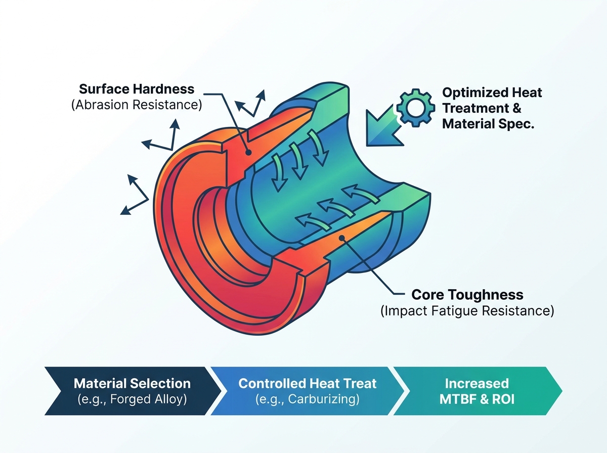
Fluid end consumables remain a leading cause of non-productive time (NPT) during hydraulic fracturing operations. They also drive massive maintenance expenditures across the energy sector. You face constant pressure to maximize operational uptime while managing increasingly abrasive slurry environments. The core specification problem centers on a delicate metallurgical balance. You must achieve exceptionally high surface hardness to resist severe proppant abrasion. Simultaneously, you need robust core toughness to survive extreme high-cycle impact fatigue. If either property fails, catastrophic component breakdown follows rapidly.
This article provides a comprehensive, decision-stage framework for engineering and procurement teams. We explore how to properly evaluate, specify, and source these critical pump components. Applying these specific engineering principles will measurably increase your Mean Time Between Failures (MTBF). You will learn how to navigate complex material selection effectively. We also detail precise heat treatment parameters and fitment risk mitigation strategies. Ultimately, you can transform consumable replacement cycles from unpredictable, costly crises into predictably managed maintenance intervals.
Selecting the right frac pump valve seat material requires matching metallurgical properties to specific pumping conditions, fluid corrosivity, and proppant abrasiveness.
Optimal heat treatment strategies must achieve precise case depth and surface hardness without compromising the ductility of the seat's core.
Upgrading to forged fluid end valve seats often yields better structural integrity and longer fatigue life compared to cast alternatives.
Deviating from OEM fluid end valve seat specifications introduces fitment risks; custom specifications must meet or exceed original dimensional and pressure tolerances.
Defining success for fluid end consumables requires moving beyond simple upfront unit costs. You should evaluate component value based strictly on continuous operating hours and proven MTBF. Every single hour of uninterrupted pumping generates critical revenue. Conversely, frequent consumable swaps destroy your operational margins. A premium component pays for itself multiple times over if it eliminates just one mid-stage maintenance shutdown.
Understanding exactly how components fail helps you specify the correct upgrades. Pumping environments actively attack metal through three primary mechanisms:
Washout and Erosion: High-velocity abrasive proppants, such as 100-mesh sand or rigid ceramic particles, scour away internal geometries. Once a microscopic fluid bypass channel forms, high-pressure fluid quickly erodes a massive washout path.
Impact Fatigue: Modern pumps operate at immense pressures, often exceeding 15,000 psi. Repetitive cyclic loading strikes the seat dozens of times per second. This relentless pounding fractures brittle metallurgical structures over time.
Corrosion: Acidic fracturing fluids, recycled produced water, and harsh chemical breakers aggressively degrade base metals. Corrosion pits create stress concentrators, which subsequently accelerate impact fatigue cracking.
Unplanned downtime represents "red money" bleeding directly from your operational budget. This metric includes not only the cost of replacement parts but also the massive sunk costs of idle crews, equipment standby rates, and delayed production. Targeted field trials establish an accurate baseline for tracking MTBF improvements. Real-world performance data easily justifies the initial premium price of advanced metallurgy. Investing strategically in better materials upfront drastically reduces these expensive, unplanned field failures.
Selecting an optimal frac pump valve seat material heavily dictates your long-term field performance. You have several distinct material categories to consider, each suited to different operational intensities.
Common industry alloys include 8620, 4140, and 4320 carbon steels. These options represent cost-effective baselines for standard pressure environments. They perform adequately under moderate pumping conditions and standard sand meshes. However, they show severe limitations in extreme abrasion applications. Highly corrosive fluids or recycled water operations also rapidly destroy standard alloy options, forcing premature replacements.
Operators increasingly demand forged fluid end valve seats for extreme duty cycles. The mechanical forging process creates a directional grain flow aligning precisely along the component's physical contours. This high-pressure compression completely eliminates internal voids and microscopic porosity. It improves overall yield strength significantly. You gain massive structural advantages over cast alternatives. Forged seats prevent catastrophic cracking and resist the intense cyclic stress generated by modern high-rate pumping schedules.
Harsh environments demand upgraded chemistries beyond standard carbon steel. High-chrome alloys and stainless variants excel in highly corrosive fluid conditions, preventing early pitting. Furthermore, forward-thinking manufacturers now integrate abrasion-resistant nano-composites into the strike zones. Engineered urethane inserts also help absorb violent mechanical impacts. These advanced inserts seal effectively against proppant embedment, extending the life of the surrounding metal matrix.
| Material Category | Common Examples | Primary Advantage | Primary Limitation | Ideal Field Application |
|---|---|---|---|---|
| Standard Alloy Steels | 8620, 4140, 4320 | Cost-effective, easily machinable | Vulnerable to extreme corrosion and erosion | Standard pressure, benign fluids, fresh water |
| Forged Alloys | Forged 8620/4320 | Superior yield strength, no internal voids | Slightly higher initial procurement cost | High-cycle pressure environments (15k+ psi) |
| High-Chrome / Stainless | 17-4 PH, Custom Chrome | Exceptional corrosion resistance | Can be brittle if improperly heat-treated | Produced water, highly acidic fluid chemistries |
| Nano-Composite / Urethane | Steel matrix + Urethane inserts | Absorbs extreme impact, seals against proppant | Temperature limits on synthetic components | High-abrasion ceramic proppants, severe washout risk |
Raw material selection only solves half the engineering puzzle. Precise thermal processing determines whether a component survives the field or shatters on day one.
Metallurgy always requires calculated compromise. A uniformly hard valve seat will inevitably shatter under continuous 15,000 psi hydraulic impacts. Conversely, a soft, highly ductile seat will wash out rapidly from abrasive proppant flow. You must balance both properties perfectly within the exact same component.
This critical process introduces carbon deeply into the surface layer of the metal. It creates a high-hardness exterior, typically reaching between 58 and 62 HRC. Crucially, the process maintains a highly ductile, shock-absorbing inner core. Specifying an optimal effective case depth matters immensely. Correct depth maximizes wear life before exposing the softer core metal. If the case depth is too shallow, the hardened shell collapses inward under pressure. If the case depth is too thick, the seat loses its vital flexibility.
Evaluate alternative thermal treatments for specific wear profiles. Carbonitriding adds nitrogen alongside carbon into the furnace atmosphere, providing enhanced surface stability and superior wear resistance against sliding friction. Induction hardening targets specific geometric zones rather than the entire component. Regardless of the method, manufacturers must control thermal distortion carefully during the quenching process. Quenching warpage ruins dimensional accuracy rapidly, leading to poor deck seating.
Never accept unverified components into your inventory. You need strict batch testing protocols. Demand rigorous microstructural analysis from vendors. Quality assurance teams must section sample components to verify exact case depth penetration. Always require verifiable material test reports (MTRs) and thermal certification from your heat-treat partners.
Precision manufacturing dictates field reliability. Even the finest metallurgy fails if the geometry does not mate perfectly with the fluid end deck.
The specific taper angle and outer diameter (OD) require absolutely flawless execution. These precise dimensions achieve a secure, leak-free interference fit inside the fluid end deck. Even microscopic deviations—often as small as a few thousandths of an inch—invite rapid fluid bypass. Once high-pressure slurry breaches the seal, it creates a washout trench, destroying both the seat and the expensive fluid end block simultaneously.
Aftermarket upgrades often sound appealing for budget optimization. However, they must match existing deck geometries flawlessly. Ensure your upgraded designs do not void manufacturer warranties. They also must not cause premature wear on mating valves, retaining springs, or discharge covers. An incorrectly specified seat height alters valve travel distance, inducing severe spring fatigue.
Always cross-reference your custom manufacturing tolerances strictly against standard OEM fluid end valve seat specifications. Deviations inevitably lead to expensive deck washouts. Evaluate your vendor's reverse-engineering capabilities thoroughly. Insist on strict ISO 9001 compliance throughout their machining and inspection processes. Vendors should utilize advanced Coordinate Measuring Machines (CMM) to validate angularity before shipping any batch.
Transitioning to a newly specified component requires a disciplined operational rollout. Rushing untested parts to the field introduces severe risk.
Testing requires scientific discipline. You must isolate variables when testing a new metallurgical formula against legacy components.
Install the new components and legacy components in alternating cylinders within the exact same pump block.
Expose both test groups to the exact same pressures, fluid chemistry, and proppant volumes.
Establish strict, standardized wear measurement intervals (e.g., inspecting every 100 pumping hours).
Define rigid replacement criteria upfront to eliminate subjective mechanic opinions.
Premium materials cannot survive poor field installation practices. Improper seating angularity destroys components instantly upon pump priming. Pre-existing deck wear completely negates any advanced material benefits, as the new seat cannot form a proper interference fit. Furthermore, inadequate cleaning prior to installation traps sand or old rust inhibitor paste. This debris prevents proper taper engagement, virtually guaranteeing a washout event.
Use a systematic approach when choosing manufacturing partners for critical fluid end components. A poor vendor disrupts your entire supply chain.
Assess domestic versus overseas manufacturing capabilities and geographic supply risks.
Demand complete heat-treatment lot traceability back to the original steel mill pour.
Verify lead time reliability through past performance references and inventory stocking agreements.
Review their raw material sourcing documentation to ensure no substandard scrap metal enters the forging process.
Successful fluid end management requires a systematic, engineering-driven evaluation framework. Start by deeply analyzing your specific operational failure modes, whether they involve abrasive washout, chemical corrosion, or impact fatigue. Select the appropriate base material chemistry tailored to your specific proppant and fluid conditions. Demand rigorous forging methods to guarantee internal structural integrity. Dictate precise heat treatment parameters that perfectly balance surface hardness and core ductility. Finally, strictly validate all physical dimensions against original equipment tolerances to ensure a flawless deck fit.
To move forward, initiate comprehensive engineering reviews with prospective metallurgical partners immediately. Request physical material certification samples for independent laboratory testing. Set up tightly controlled, side-by-side field trials across diverse wellpads. Measure the results meticulously, document the MTBF improvements, and ultimately scale the best-performing solutions across your entire pumping fleet.
A: Most high-performance applications require a carburized surface hardness between 58 and 62 HRC. This exterior layer resists severe proppant abrasion. However, the internal core must remain much softer, typically around 30 to 40 HRC. A ductile core absorbs extreme hydraulic impact forces, preventing the seat from shattering under high-cycle loading.
A: Forging creates a directional grain flow aligning specifically to the component's geometry. This physical compression eliminates microscopic internal voids commonly found in cast alternatives. As a result, forged pieces exhibit significantly higher yield strength and superior fatigue resistance. They prevent catastrophic crack propagation during 15,000+ psi cyclical stress.
A: Nano-composites provide localized structural reinforcement in critical high-wear zones. They integrate directly into the metal matrix or primary seal areas. This technology delays erosive washout substantially without altering the primary steel geometry. The composites absorb abrasive energy better than standard steel, directly extending the Mean Time Between Failures.
A: You should only deviate when addressing chronic, documented failure modes in specific geographical formations. Valid reasons include upgrading extreme pressure requirements or mitigating highly corrosive, proprietary fluid chemistry issues. Always ensure your custom specification maintains exact dimensional taper tolerances to prevent deck damage and warranty voidance.


