
Views: 0 Author: Site Editor Publish Time: 2026-09-03 Origin: Site


Hydraulic systems operate under extreme, high-stakes conditions. Even microscopic deviations in a turned component can cause catastrophic leaks. They can trigger massive pressure drops or cause immediate system failures under 3,000+ PSI loads. Moving from a successful prototype to full-scale mass production introduces hidden risks. You face unpredictable variables like rapid tool wear, thermal expansion, and inconsistent material batches.
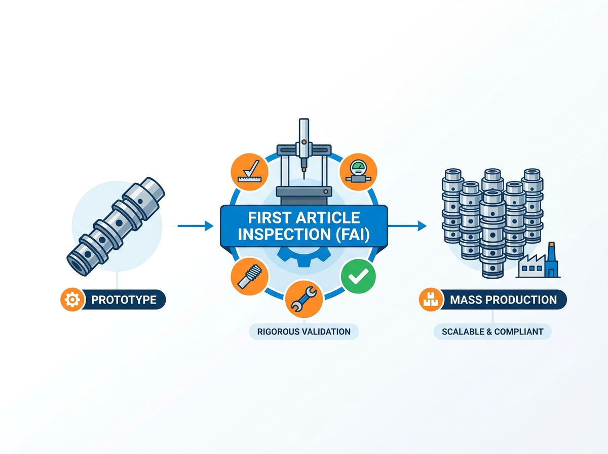
A successful single part does not guarantee stable volume manufacturing. A rigorous pre-production inspection framework acts as your strongest defense. Anchored by First Article Inspection (FAI), it remains the only verifiable way to de-risk high-volume manufacturing. This systematic approach ensures strict, repeatable compliance with engineering specifications. In this guide, you will learn how to evaluate critical dimensions, leverage advanced metrology, and secure reliable mass production.
Surface finish dictates seal integrity: Verification of Ra and Rz values using profilometers is non-negotiable for O-ring grooves and mating surfaces.
GD&T trumps simple dimensions: Concentricity, cylindricity, and runout are critical for dynamic hydraulic spools and cylinders.
Material validation prevents field failure: Pre-production must include Positive Material Identification (PMI) and hardness testing to verify alloy properties under pressure.
A documented FAI report is your go/no-go gate: Do not approve mass production without a comprehensive, dimension-by-dimension verification report from your machining partner.
The consequences of skipping strict pre-production checks are severe. You must weigh the relatively low upfront cost of rigorous inspection against the staggering liabilities of field failures. A single failed hydraulic seal can halt an entire production line or disable heavy construction machinery. This results in costly downtime, hazardous fluid spills, and expensive product recalls. Proper inspection prevents these financial disasters.
You must also recognize the gap between prototyping and production. A successful single prototype proves the basic design works. However, it does not guarantee stable mass production over thousands of cycles. Continuous machining generates significant heat. This thermal drift causes machine components to expand slightly, which shifts cutting tolerances. Tool inserts also degrade over time. These combined factors mean the thousandth part often looks very different from the first part. You must account for these variables before approving a full production run.
You need clearly defined success criteria. Knowing what "ready for production" looks like eliminates guesswork. This means demanding 100% dimensional adherence on the first batch. You also need fully verified material certificates from your vendor. Finally, you should map out a clear tool-change schedule. This schedule dictates exactly when cutting inserts must be replaced to maintain tight tolerances across high volumes.
Implementing a flawless CNC turned hydraulic parts inspection requires looking beyond basic calipers and micrometers. Hydraulic applications demand micro-precision. Let us examine the specific dimensions you must evaluate before cutting metal at scale.
Standard visual inspection always fails when evaluating hydraulic seals. A surface might look smooth to the naked eye but harbor microscopic peaks and valleys. These imperfections easily shred O-rings under high pressure. You must evaluate specific roughness metrics. Ra (Average Roughness) measures the overall texture. Rz (Maximum Peak to Valley Height) detects sharp spikes. Monitoring both metrics is specifically required for dynamic and static seal glands to prevent slow fluid weepage over time.
Simple diameter checks do not guarantee part functionality. You must strictly enforce GD&T principles to ensure components fit and slide together perfectly.
Concentricity: This ensures the inner and outer diameters share the exact same central axis. Without perfect concentricity, piston rods suffer from uneven wear. They will eventually bind inside the cylinder and destroy the internal seals.
Cylindricity and Roundness: Hydraulic valve spools operate with incredibly tight clearances. If a spool is slightly oval rather than perfectly round, fluid will bypass the valve internally. This internal leakage causes uncontrollable pressure drops across the system.
Hydraulic fluid ports rely on complex thread standards. You often encounter SAE, NPTF, BSPP, or UNJ thread types. A poorly cut thread will weep fluid or strip entirely under load. You cannot inspect these adequately using visual methods. Quality teams must use calibrated go/no-go ring and plug gauges. These tools confirm pitch diameter, thread depth, and flank angles match exact international standards.
Success in hydraulic component precision machining relies entirely on robust, advanced measurement tools. Relying on outdated equipment introduces fatal errors into your production line. Quality assurance labs need specific technologies to validate complex geometries.
A CMM uses highly sensitive touch probes to map a physical part in three-dimensional space. It remains the gold standard for validating complex geometries and tight-tolerance bores. You rely on a CMM to measure angular alignments with sub-micron accuracy. It easily detects spatial deviations missed by standard hand tools, ensuring mating components assemble smoothly.
Certain internal features pose severe measurement challenges. Deep O-ring groove depths and internal chamfer angles block mechanical CMM probes. Surface profilometers drag a diamond-tipped stylus across the metal to graph surface topographies instantly. Optical comparators project a highly magnified silhouette of the part onto a screen. This allows inspectors to verify tiny thread roots and obscure internal angles visually.
Even perfectly machined parts will fail if made from the wrong alloy. Material properties matter just as much as dimensions.
PMI Scanners: Positive Material Identification scanners use X-ray fluorescence. They confirm the exact elemental composition of your metal. This ensures you received the correct grade of stainless steel, brass, or carbon steel. Proper material guarantees necessary corrosion resistance and yield strength.
Hardness Testing: Hydraulic components often undergo post-turning heat treatments. Rockwell or Brinell hardness testing verifies the metal reached the correct hardness. This ensures the component will comfortably withstand intense operating pressures without deforming.
Table 1: Metrology Tools Comparison for Hydraulic Parts
| Metrology Tool | Evaluated Feature | Accuracy Level | Common Application |
|---|---|---|---|
| Coordinate Measuring Machine (CMM) | GD&T, Concentricity, True Position | Sub-micron (Very High) | Valve bodies, complex bore alignments |
| Surface Profilometer | Ra and Rz Roughness Values | Nanometer scale | O-ring grooves, cylinder bore walls |
| Optical Comparator | Angles, Thread profiles | High | Fluid port threads, tiny chamfers |
| XRF PMI Scanner | Alloy composition | High (Elemental % ) | Verifying raw material stock |
When optimizing CNC turning for hydraulic components, the FAI process sets the entire foundation. You use this formal procedure to prove the manufacturing setup can consistently produce parts matching the blueprint.
FAI is not merely checking a single part. It represents a strict verification framework. You typically utilize aerospace standards like AS9102 or automotive PPAP guidelines. These frameworks baseline the first part coming off the production line. They force the machinist and quality team to verify every single process variable before proceeding to mass production.
The FAI process creates your master control plan. You must document the "golden part" exhaustively.
The quality engineer numbers every single dimension and note on the CAD drawing.
They measure each corresponding feature on the physical part.
They record the actual measured value alongside the allowed tolerance limit.
They map the approved physical part to a documented inspection report.
This rigorous documentation ensures nothing gets overlooked. It proves the machining center understands the design intent perfectly.
Inspectors use the initial small-batch run to calculate statistical process capability, known as Cpk. You measure a sample group of parts to see how dimensions drift across the batch. A high Cpk proves the CNC turning process is stable. It shows the machine can handle high-volume output without requiring constant, risky manual adjustments from the operator.
Not all machining facilities possess the capability to handle high-pressure hydraulic requirements. You must vet prospective manufacturing partners ruthlessly before awarding a mass production contract.
You should always prioritize partners operating climate-controlled, in-house quality assurance labs. Precision metals expand and contract based on room temperature. A temperature-controlled lab guarantees measurement stability. Furthermore, in-house labs provide immediate feedback loops to the shop floor. If a dimension starts drifting, the lab alerts the machinist instantly. Outsourcing metrology causes severe delays and risks producing thousands of scrap parts.
Great vendors communicate proactively. Look for partners who openly flag manufacturability issues. They should provide strict Design for Manufacturability (DFM) feedback. A reliable partner will point out impossible tolerances or out-of-tolerance risks before any metal is cut. This transparency saves you time, prevents redesign costs, and builds long-term trust.
You must ensure the vendor provides full lot traceability. Request Mill Test Reports (MTRs) for all raw materials. These documents must link directly back to the FAI report and the specific batch of parts. If a field failure occurs years later, you need this paper trail to trace the exact steel heat used.
Do not simply ask for a price quote. Advise your procurement team to request an anonymized FAI report from prospective vendors. Evaluating their past documentation rigor reveals their true capabilities. A clean, detailed FAI report proves they treat quality control seriously.
Mass production success depends entirely on the rigorous pre-production inspection phase. Cutting corners during the initial setup inevitably leads to disastrous field failures, fluid leaks, and ruined equipment. You cannot afford assumptions when dealing with high-pressure fluid dynamics.
Precision metrology, strict GD&T adherence, and comprehensive material validation remain required safeguards. By enforcing a strict First Article Inspection process, you establish a predictable, stable manufacturing rhythm. You ensure every component rolling off the CNC lathe perfectly matches the original engineering intent.
Protect your next hydraulic project today. Upload your CAD files to a trusted manufacturing partner for a thorough manufacturability review. Contact an experienced engineering team to discuss customized FAI protocols tailored specifically to your unique hydraulic components.
A: Hydraulic cylinder bores typically require an Ra (Average Roughness) finish between 0.1 to 0.4 µm. The exact specification depends heavily on the seal type being used. PTFE seals require different surface textures compared to polyurethane seals. Operating pressure also dictates how smooth the bore must remain to prevent fluid weepage.
A: No, an FAI report does not guarantee continuous perfection. FAI strictly validates the initial machine setup, tooling, and programming process. Ongoing in-process sampling, known as Acceptable Quality Limit (AQL) inspections, remains necessary. Routine checks catch tool wear and thermal drift during continuous mass production.
A: Concentricity measures how perfectly two cylindrical features share a central axis. It is difficult because you cannot simply use calipers. It requires referencing an exact, invisible datum axis. Inspectors must use advanced Coordinate Measuring Machines (CMM) or precision V-blocks paired with highly sensitive dial indicators to verify it accurately.
A: You should demand comprehensive Mill Test Certifications (MTRs) tied directly to your specific production batch. Additionally, utilize non-destructive testing. X-ray Fluorescence (XRF) Positive Material Identification (PMI) testing allows you to verify the exact elemental composition of the finished articles without damaging them.


