
Views: 0 Author: Site Editor Publish Time: 2026-10-04 Origin: Site


Fluid leaks, warranty claims, and catastrophic system failures in hydraulic equipment frequently trace back to improperly specified or machined seal grooves. Standard turning tolerances rarely suffice for high-pressure fluid power applications. Achieving reliable seals requires precise control over microscopic geometry. O-rings must seat perfectly to prevent fluid bypass under extreme pressure conditions. This article serves as a technical guide for engineers and procurement teams. We will help you lock down critical specifications and mitigate common manufacturing risks. You will learn how to evaluate machining partners effectively to ensure leak-free performance. Expect to uncover the hidden pitfalls of internal geometry generation. By mastering these engineering details, you can prevent costly field failures before they start. Proper planning ensures seamless component assembly and long-term durability in the field.
Success in sealing relies heavily on specifying the correct root radii, lead-in chamfers, and surface finishes, not just the width and depth of the groove.
Dynamic and static seals require vastly different O-ring groove machining tolerances and surface finish controls (Ra).
Evaluating a manufacturing partner requires looking beyond machine capabilities to their metrology tools, specifically how they measure internal groove geometry and micro-finishes.
Clear RFQ documentation that explicitly calls out edge breaks and extrusion gaps prevents costly misalignment and assembly shear.
Minor deviations in groove geometry generate severe consequences. An oversized groove allows seal extrusion during high-pressure spikes. High pressure forces the elastomeric material into tiny clearances. This pinches the rubber and destroys the seal entirely. Conversely, an undersized groove causes nibbling or spiral failure. Spiral failure happens when part of the O-ring rolls while another part slides. This twists the seal until it breaks. These minor deviations directly trigger expensive fluid leaks. Equipment downtime often costs thousands of dollars per hour. Proper geometry prevents these catastrophic failures.
The operating environment directly dictates the required tolerance. Dynamic applications involve constant motion. High-cycle dynamic cylinders demand extremely tight control over concentricity. They also require pristine surface finishes. Rough finishes act like sandpaper against moving rubber. Engineers must tightly control O-ring groove machining tolerances to prevent abrasive seal wear. Static environments prove more forgiving. Static end caps simply hold two stationary parts together. While static seals still require precision, they do not face constant friction. You can apply slightly looser tolerances here without sacrificing reliability.
A significant gap often exists between CAD models and actual turned parts. CAD software creates perfect internal corners effortlessly. Machine tools rely on physical cutting inserts. These inserts have specific nose radii and wear rates. Engineers must explicitly tolerance the groove root and side walls on their drawings. Relying on general title block tolerances invites disaster. Standard block tolerances rarely account for the specific needs of elastomeric seals. Clear explicit instructions bridge the gap between digital design and manufacturing reality.
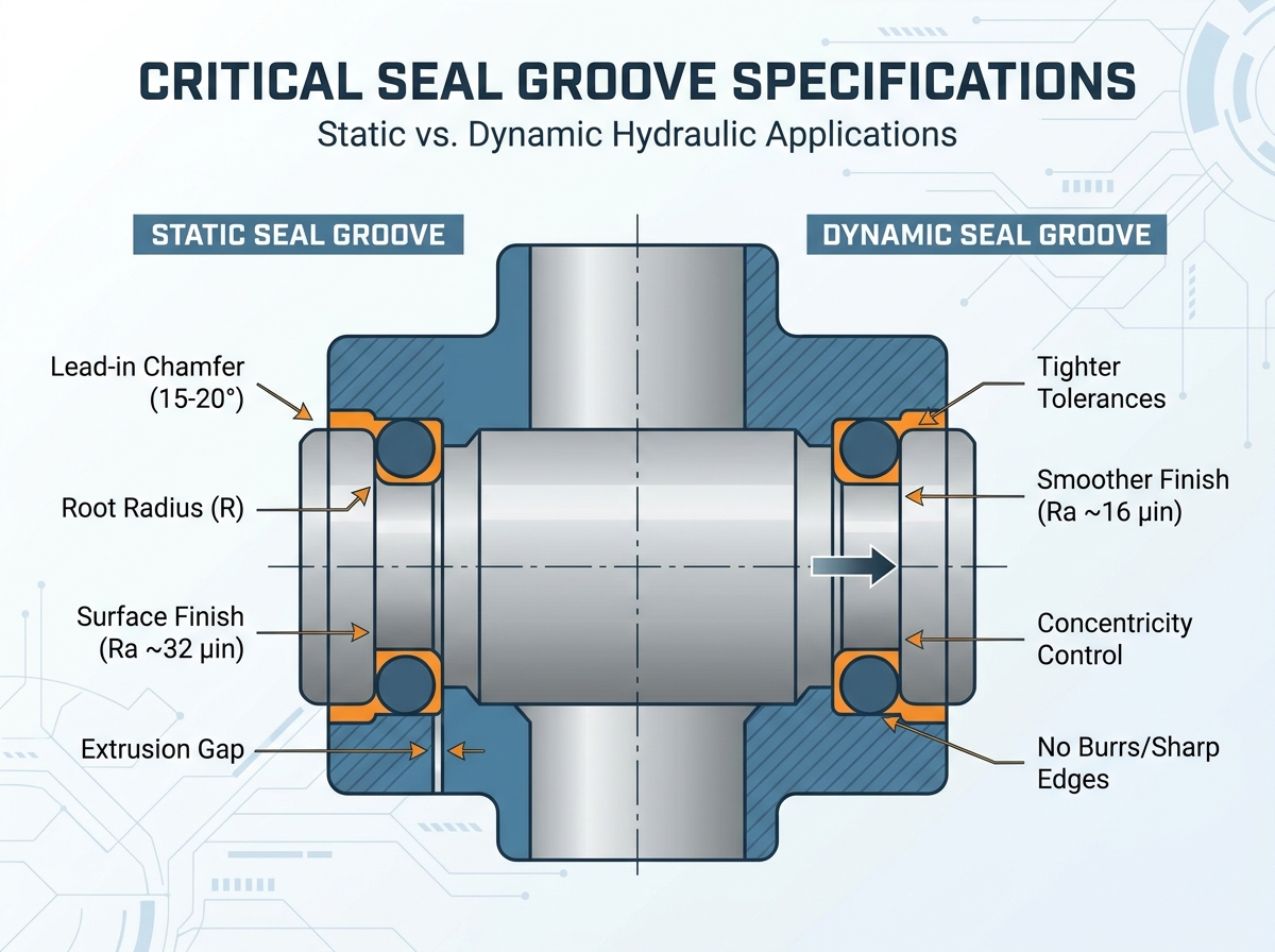
Properly sizing the groove width and depth determines seal longevity. Grooves must allow for seal swell. Hydraulic fluids often cause rubber to expand. Thermal expansion also increases the seal volume. If the groove lacks extra space, the expanding rubber exerts massive outward force. This can deform thin-walled components. Furthermore, engineers must minimize extrusion gaps. The extrusion gap is the clearance between the mating metal parts. High pressure easily forces the O-ring out through large gaps. Tight diametral clearances keep the seal contained.
Sharp internal corners ruin hydraulic components. They create severe stress concentrations in the metal body. These stress risers often lead to fatigue cracking under cyclic pressure. Sharp corners also provide uneven seating for the seal. Rubber cannot fill a perfectly sharp corner. This leaves tiny air pockets that cause instability. You must specify minimum and maximum radii. Standard handbooks, like the Parker Hannifin O-Ring Handbook, provide strict guidelines. Using a proper radius ensures the seal compresses evenly across its cross-section.
Assembly damage destroys more seals than operational wear. Mechanics must push elastomeric seals past metal edges during assembly. Without a proper transition, sharp edges slice right through the rubber. You must specify lead-in chamfers on all leading edges. A 15° to 20° angle works best. This gentle slope safely compresses the O-ring as it enters the bore. It prevents shearing and keeps the seal intact before the equipment ever powers on.
Surface finish directly impacts sealing ability. You must specify distinct micro-inch requirements for different faces. The groove bottom serves as the primary sealing surface. It requires a much smoother finish than the side walls. Side walls mainly provide mechanical support rather than primary fluid containment.
Static sealing applications typically require a 32 µin Ra finish. The rubber remains stationary and fills the microscopic valleys. Dynamic applications require a much smoother finish. Dynamic grooves often need 16 µin Ra or better. Rough dynamic grooves will quickly shred moving elastomers.
Standard Surface Finish Guidelines for O-Ring Grooves
| Application Type | Groove Bottom (Ra) | Side Walls (Ra) | Primary Failure Risk if Ignored |
|---|---|---|---|
| Static (Liquid) | 32 µin (0.8 µm) | 63 µin (1.6 µm) | Micro-weeping under high pressure |
| Static (Gas/Vacuum) | 16 µin (0.4 µm) | 32 µin (0.8 µm) | Gas permeation and rapid pressure loss |
| Dynamic (Hydraulic) | 16 µin (0.4 µm) | 32 µin (0.8 µm) | Abrasive wear and premature seal degradation |
| Dynamic (Pneumatic) | 8 µin (0.2 µm) | 16 µin (0.4 µm) | Rapid frictional wear due to lack of lubrication |
Cutting deep internal grooves presents major physical challenges. Machinists must use specialized boring bars. Long tool overhangs act like metal springs. Cutting forces push the tool away from the workpiece. This phenomenon causes tool deflection. Deflection leads to severe chatter and vibration. Chatter leaves a wavy surface finish behind. These microscopic waves create direct leak paths for hydraulic fluid. Controlling deflection during hydraulic seal groove machining requires highly rigid setups and optimized feed rates.
Machining operations naturally create burrs. When a grooving insert exits the cut, it often folds metal over the edge. These microscopic burrs act like razor blades. Uncontrolled burrs will destroy elastomeric seals during installation. You cannot rely on operators to simply "deburr" based on assumptions. You must detail deburring or edge-break requirements directly on the drawing. Specify an exact edge break dimension, such as 0.005" maximum radius. This removes ambiguity and protects the seals.
Different metals behave differently during internal grooving operations.
Soft Alloys (Aluminum/Brass): These materials tend to stick to the cutting tool. This creates a built-up edge (BUE). BUE alters the tool geometry and tears the material surface. It results in poor finishes and torn side walls.
Hardened Steels/Stainless: These tough materials generate extreme heat. They cause rapid tool wear. As the insert wears down, the groove dimensions change. This rapid wear alters critical tolerances mid-batch. Machinists must monitor tool life meticulously.
Producing reliable CNC turned hydraulic fittings requires advanced manufacturing technology. Rigid, multi-axis CNC lathes provide the necessary stability. Machine rigidity prevents chatter during heavy grooving cuts. High-pressure coolant systems remain non-negotiable. Deep internal grooves trap metal chips easily. If the tool recuts these chips, it destroys the surface finish instantly. High-pressure coolant blasts the chips out of the groove. It protects the critical sealing surfaces from damage.
A vendor must mathematically prove they met your specification. Standard measurement tools fall short here. Calipers cannot measure internal groove surface finish. They also cannot accurately measure tiny internal root radii. You must look for partners utilizing advanced metrology equipment. Optical comparators project a magnified shadow of the groove profile. Profilometers measure microscopic surface roughness. Specialized bore micrometers confirm exact diametral dimensions. Proper QA guarantees field performance.
Repeatability defines quality in fluid power components. Process traceability ensures part number one thousand matches part number one. A good partner provides complete material certifications. They supply First Article Inspection (FAI) reports for every new setup. They also utilize documented tool-life management systems. Tool-life management forces the machine to change inserts automatically before wear affects the tolerance. Traceability prevents out-of-spec parts from ever leaving the facility.
Vague engineering drawings cause manufacturing failures. Avoid generic notes like "machine to standard" entirely. Machinists will interpret generic notes differently. You must require specific callouts for every critical feature. Detail the groove width, root radius, and surface finish individually. Point specifically to the faces of the groove that require these controls. Clear callouts eliminate guesswork. They force the machining partner to inspect the exact features you care about most.
Industry standards provide a universal language for engineers and machinists. Explicitly cite which industry standards your groove dimensions follow. Standards like ISO 3601 or AS568 dictate specific dimensional relationships. Referencing these frameworks helps the manufacturer understand the design intent. It also gives them a baseline for troubleshooting if dimensional conflicts arise during programming. Clear standard references streamline the entire quoting and production process.
Manufacturers need to understand the final application environment. Clearly state your testing and validation plans on the RFQ. Will the parts undergo pressure testing? Will they face extreme burst testing? Describe specific assembly procedures if they involve unique tools. This transparency helps the machining partner understand the functional requirements. If they know the part faces 10,000 PSI, they will apply tighter process controls to the sealing surfaces.
Preventing hydraulic leaks starts at the drafting board. Engineers must create precise, manufacturing-aware specifications.
Root radii, lead-in chamfers, and precise surface finishes matter just as much as overall groove dimensions.
Material behavior dictates machining strategy. Soft alloys risk built-up edge, while hard metals risk rapid tool wear.
Partnering with a machine shop experienced in tight-tolerance fluid power components reduces iterations, ensures field reliability, and improves final product quality.
A: Standard finishes depend heavily on the application environment. Static applications typically require a surface finish between 16 and 32 µin Ra. Dynamic applications involve constant motion and require a smoother finish, generally ranging from 8 to 16 µin Ra. Rougher finishes will cause abrasive wear on moving elastomeric seals.
A: O-rings usually shear during assembly due to sharp metal edges. This occurs when drawings lack a proper lead-in chamfer (typically 15° to 20°). It also happens when microscopic burrs remain on the groove edge. Machinists must explicitly break all sharp edges to protect the rubber during installation.
A: Yes. With highly rigid tooling, appropriate carbide inserts, and optimal feeds and speeds, CNC turning can achieve dynamic finishes. High-pressure coolant also helps clear chips to prevent surface scoring. However, engineers may specify secondary polishing or roller burnishing for extreme high-cycle dynamic applications.
A: Standard calipers cannot accurately reach inside small internal grooves. Quality machine shops use specialized inspection tools instead. Optical comparators verify the geometry and root radii using light projection. Contour tracers map the exact internal profile. Specialized internal profilometers physically drag a diamond stylus across the groove to measure micro-roughness.


